The General Register Organization in computer architecture is a model in which multiple general-purpose registers are available to the CPU instead of just one accumulator. Such a system enables the 'machine' to carry out data operations faster and effectively as the access to memory is reduced for temporary data storage.
In this article, we will look into the characteristics, pros, and cons of General Register Organization and, additionally, it includes practical usages in CPU designs.
In General Register Organization, the CPU has a set of general-purpose registers in which it temporarily stores data during program execution. Those registers are small, super-fast storage places inside the CPU. Compared to accumulator-based architectures, where data is temporarily stored in a single accumulator, this organization uses multiple registers, each of which can store different kinds of data like integers, floating-point numbers, addresses, and control information.
The adoption of these general-purpose registers results in the acceleration of data processing because the time it takes to access data from the registers is considerably less than that of the memory. Also, most CPU instructions operate on the data stored in registers directly, which gives the computation further a speed-up.
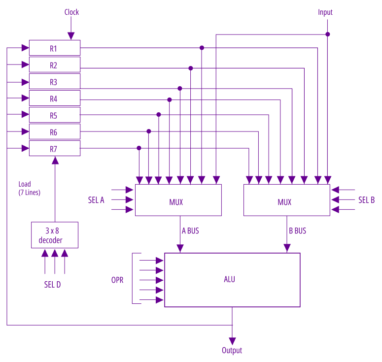
Below is the general register organization diagram showing the connection of registers, ALU, and buses:
The features of the General Register Organisation are:
1. Registers
The General Register Organization has the CPU with several general-purpose registers. These are the registers that are used for storing data which is actively being processed, thus providing a very quick access to the data as compared to the slower memory storage. This process is fundamental in enhancing performance, especially when the variables that are accessed frequently and the intermediate results are used.
2. Operand Access
Operands are accessed directly from the registers by the CPU thus there is no need to constantly access the slow memory. Data retrieval and manipulation become faster by using the registers and consequently program execution is made faster. The general-purpose registers work as a temporary storage for the operands to be used in arithmetic and logical operations.
3. Data Processing
Here, the CPU is allowed to perform the desired arithmetic and logical operations directly on the data stored in the registers without going through the middle storage. This method lessens the time that is spent on the movement of data thereby the execution of the whole program gets faster.
4. Instruction Format
The instruction format of General Register Organization normally contains the fields that indicate the operation to be done and the operands (which most of the time are register addresses). The main advantage of these instructions is that they are less space-consuming which allows the efficient use of the CPU’s available registers.
5. Context Switching
One of the main aspects of General Register Organization is that it can provide the support for context switching. The CPU, when it changes from one process to another, stores the details of its general-purpose registers to memory and then, when the process is continued, it retrieves the data. Thus, the CPU time can be given to several processes which in turn, keep their states unchanged.
Usually, in register architecture, choosing and coding registers are the basic operations that allow the flow of data to different CPU parts (for example, the ALU, instruction registers, and stack control registers (SCR)) in a convenient way. Through certain areas in the command structure, also called register selection fields, this operation is executed.
A typical register organization diagram illustrates how registers are connected to the ALU via buses and how the decoder interprets selection fields to direct data movement. When an instruction is executed, the control unit uses the register selection field encoding to determine which registers will serve as sources and destinations for the operation.
Register Selection Fields and Encoding
Each instruction contains specific bits—known as register selection fields—that encode which registers are to be used. For example:
- SELA: Selects the source register for ALU input A.
- SELB: Selects the source register for ALU input B.
- SELD: Selects the destination register to store the ALU result.
These fields are typically three bits each, allowing selection among up to eight registers (e.g., R1 to R7, plus input or output). The encoding works as follows:
Binary Code SELA SELB SELD 000 Input Input None 001 R1 R1 R1 … … … … 111 R7 R7 R7
A decoder interprets these encoded fields and activates the appropriate register lines, ensuring only the selected registers participate in the current operation. This mechanism is essential not only for arithmetic and logic operations in the ALU but also for managing context switching, where the state of all registers—including instruction registers and stack control registers (SCR)—must be saved and restored efficiently.
Role in Data Flow and Context Switching
The efficient and encoded register selection facilitated the data flow through CPU to be without interruptions, thus the data flow sustained quick context switching. In a context switch, the addressing method through encoding facilitates that all registers (the program counter, system control registers, and instruction registers) are addressed in an orderly way, thus the computational state being preserved for multitasking environments.
By detailing the implementation of register selection field encoding, including the use of decoders and control words, your article will provide readers with a clear understanding of how register organization underpins fast and reliable CPU operations.
In general register organization, a control word is a binary-encoded instruction that directs the CPU on how to execute a specific operation. The control word acts as a bridge between the instruction format and the internal hardware, determining how operands are selected, which operation is performed, and where results are stored.
Concept of the Control Word
The binary data that are introduced from the outside into a computer in order to change the behaviour of the system are known as control words. Every bit or even several bits of a control word relate to some particular control signal or selection in the central processing unit (CPU). These signals along with the control word which is the main one, perform the data flow, register selection as well as operator execution, thus the control word is the essential one when it comes to commanding complex instructions.
Structure of the Control Word
The structure of the control word typically mirrors the instruction format used by the CPU. A standard control word may include the following fields:
- Register Selection Fields: Bits that specify which registers will serve as source and destination for the operation (e.g., SELA, SELB, SELD).
- Operation Field: Bits that define the precise operation to be performed (such as addition, subtraction, or logical operations).
- Other Control Bits: Additional bits may control data routing, enable stack organization features, or manage special registers.
For example, a control word in a CPU with seven general-purpose registers might be organized as follows:
- 3 bits for SELA (source register A)
- 3 bits for SELB (source register B)
- 3 bits for SELD (destination register)
- 4 bits for the operation code
This totals to a 13-bit control word, where each group of bits acts as a binary selection input to the corresponding hardware component.
Managing Operations with the Control Word
The control word is the main element that directly governs the operations in a general register organization. When the processor gets an instruction, it is decoded into a control word.
The data paths which are enabled by the binary selection inputs, select the operands that are needed from the register set, and also specify the operation that is to be performed. For instance, the control word for a stack might have additional commands to manage the stack pointer or perform stack-specific operations.
By encoding all necessary information in a compact binary format, the control word ensures that every operation—whether arithmetic, logic, or data movement—is executed efficiently and accurately within the CPU.
In general register organization, the Arithmetic Logic Unit (ALU) is responsible for performing a variety of arithmetic and logic operations directly on data stored in registers. These operations, called micro-operations, are the fundamental steps that allow the CPU to execute complex instructions efficiently.
ALU Operations Encoding and the 14-bit Control Word
The selection and execution of ALU operations are managed through a 14-bit control word. This control word includes fields for register selection as well as an ALU operation selector (OPR). The OPR field encodes the specific operation to be performed, such as addition, subtraction, logical AND, OR, XOR, increment, decrement, and shifting operations.
For example, the encoding might look like:
- OPR = 00010: Add A + B
- OPR = 00101: Subtract A - B
- OPR = 01010: OR A and B
This encoding ensures precise control over the ALU's behavior for each instruction.
Operand Manipulation and Involved Registers
ALU operations rely on various registers to provide operands and store results:
- AC (Accumulator): In certain systems, it is frequently the default operand or result register.
- AR (Address Registers): Store the memory addresses for accessing the data.
- DR (Data Registers): Hold the data temporarily that is going to be processed.
- IR (Index Registers): Operate the indexed addressing and the control of the loop.
- MDR (Memory Data Registers): The CPU memory interface for data transfers.
- PC (Program Counter): Indicates the next instruction to be carried out.
During an operation such as R1 ← R2 + R3, the control word specifies:
- Which registers supply the operands (R2 and R3)
- Which register will receive the result (R1)
- Which operation the ALU should perform (addition, via the OPR field)
ALU Micro-Operations in Register-Register Reference Architecture
In a register-register reference architecture, all operands must reside in registers, and the results are also stored in registers. This design enables the ALU to perform micro-operations quickly, as it avoids the latency of memory access. Common ALU micro-operations include:
- Data transfer between registers
- Arithmetic operations (add, subtract, increment, decrement)
- Logical operations (AND, OR, XOR, complement)
- Shift operations (left, right)
Each micro-operation is triggered by a specific combination of control word fields, ensuring that the correct registers and ALU functions are engaged for each instruction.